
The new NetStork version has just come out! The 11th edition brings many improvements, such as enhanced fiber splices modeling. See the detailed changes below!
Optical connectors
The 11th version introduces many innovations for modeling optical splices. It’s now possible to inventorize elements such as fiber trays, patch-panels, and pigtails. Another new feature is modeling fiber-port connections, similarly to the fiber-fiber connections that already existed in previous versions.
Trays
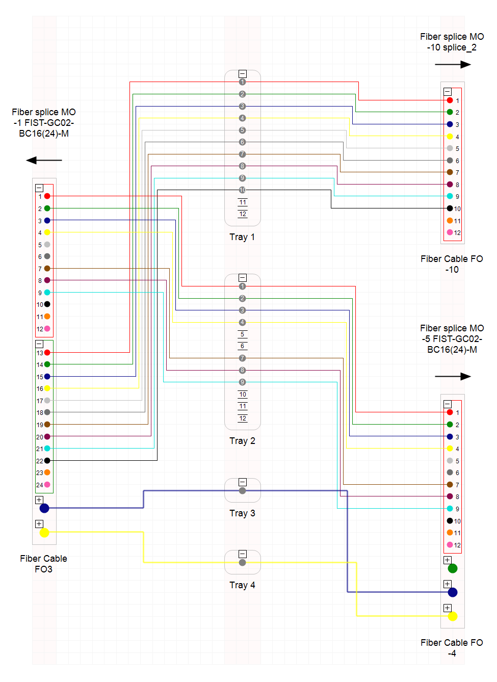
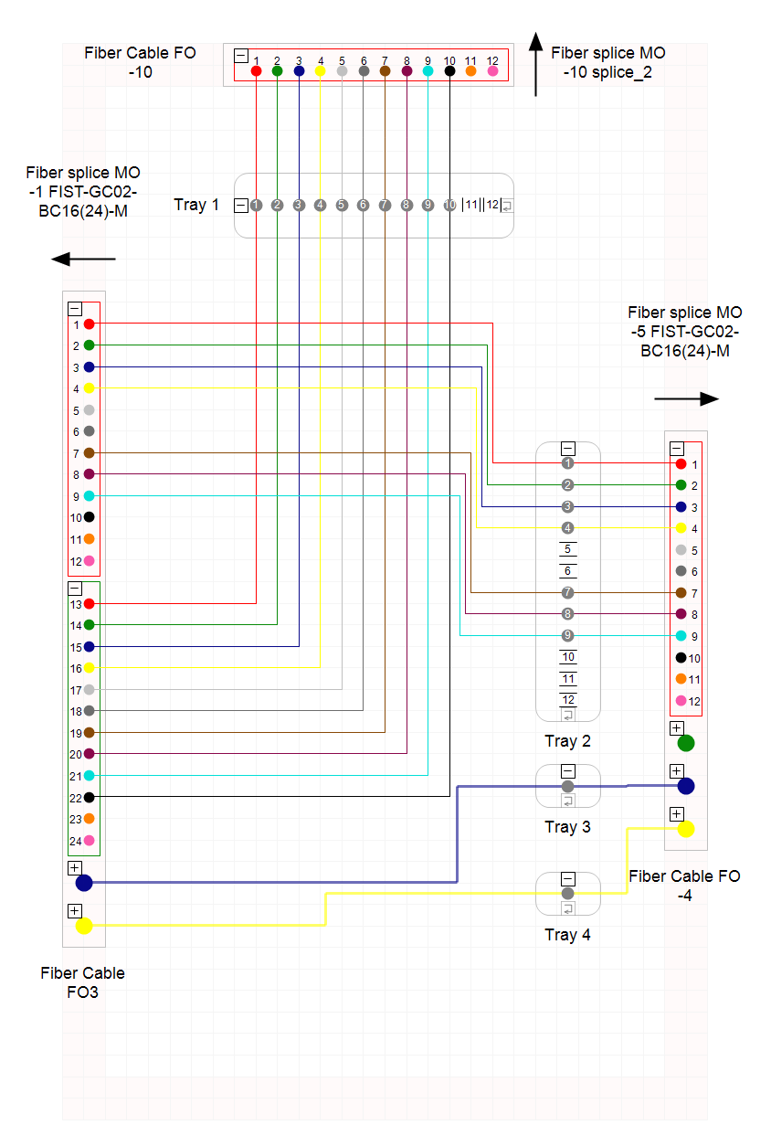
Fiber Trays are elements that allow us to arrange welds in fiber splices and fiber cable boxes. In the newest version, it’s possible to add trays inside those two kinds of objects. Thanks to this, the information about which trays hold particular connections can be stored in the system and visualized on the optical schemas. There are two ways for creating such visualization:
Standard, with the ODF rack layouts that are currently also available for the optical splices.
With floating splices that are positioned on the diagram similarly to the splitters.
Patch-panels and pigtails
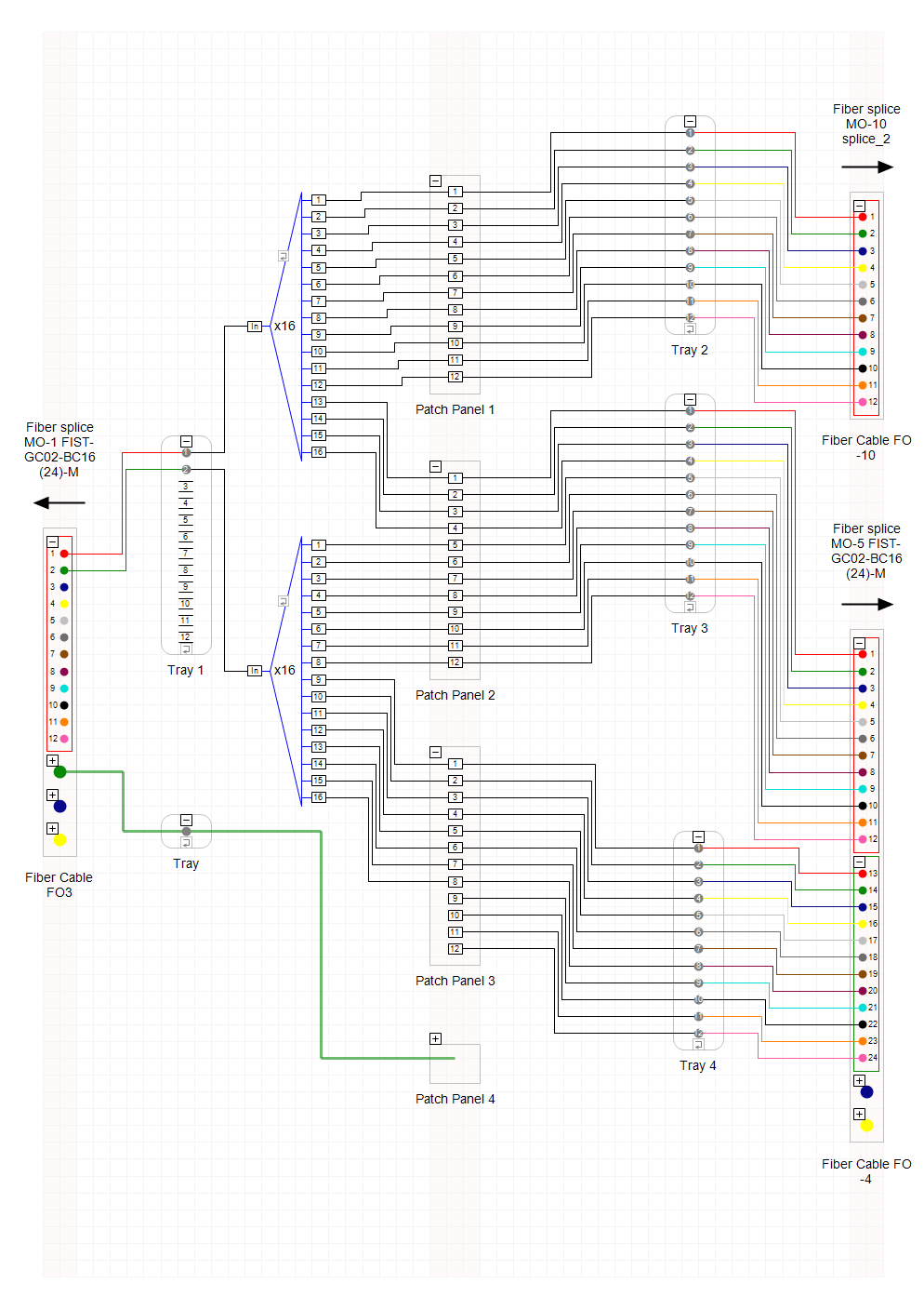
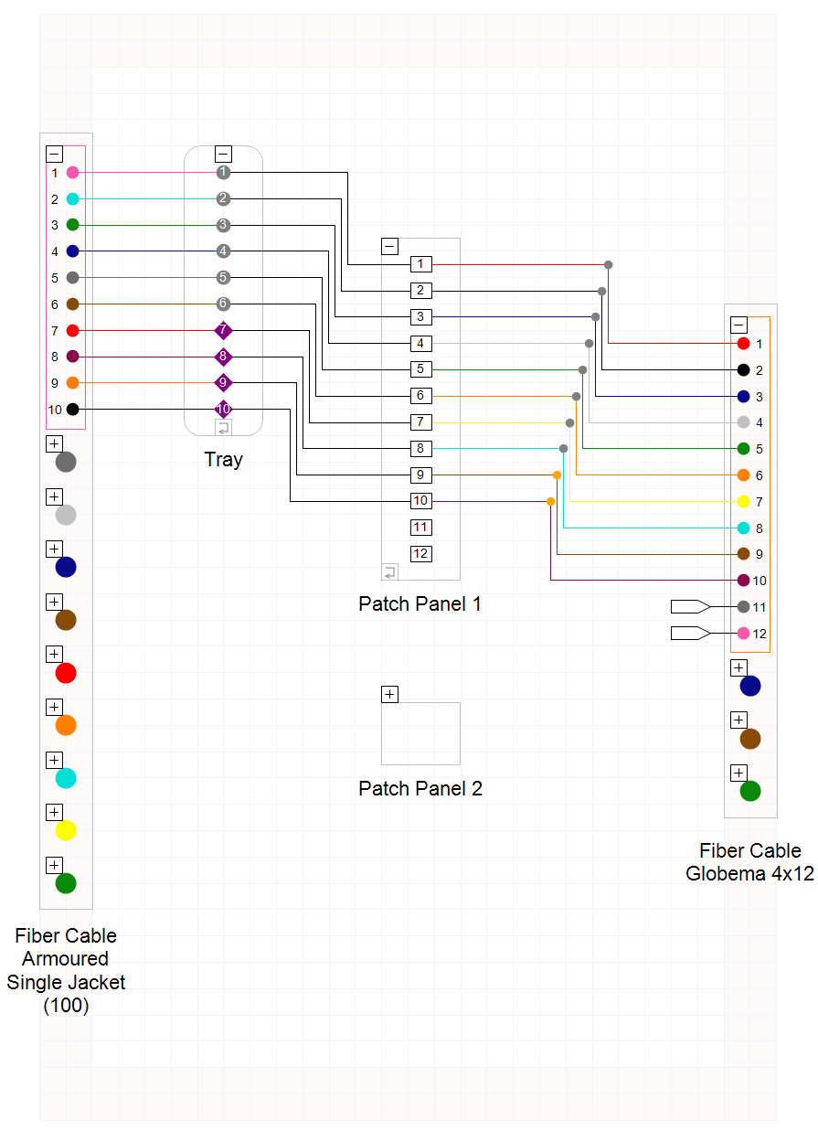
In the 11th version, we introduced a patch-panel object with a list of ports that can have pigtails connected. You can add many patch-panels to a splice or box, just like in the reality. You can also automatically generate patch-panels and trays based on data from the specification.
Click to enlarge
Patch-panels on optical schemas can be floating like fiber trays. Thanks to introducing patch-panels there is no need for modeling fiber splices with patch-panels using ODF shelf and converting fiber splices to such objects. Currently, any number of patch-panels can be added to any fiber splice, just like in the reality.
To make switching to the new model easier, we added a special operation for converting such “ODF Shelves” to fiber splice with patch-panel. Thanks to this, changing objects and switching all the connections can be done with a single click.
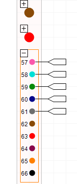
Sometimes it’s necessary to inventorize pigtails that are welded in the fiber splice and haven’t been connected to the patch-panel yet. It’s now possible to do that. The diagram below shows pigtails visualized with a plug symbol attached to each fiber that has a welded pigtail.
Click to enlarge
Modeling fiber-port connections
In NetStork 11 we introduced the possibility for modeling fiber-port connections which is useful in order to stocktake type and parameters of such connections, such as attenuation or type of the used pigtail. Fiber-port connections are modeled using a “fiber connection” object and visualized on the schema as a weld symbol.
Click to enlarge
Visualizing network objects on the building structure schema
We’ve added the following network elements visualization to the building structure diagram: ODF Racks, ODF Shelves, devices, optical splices, and boxes. Cable connections between these objects are also drawn. This results in a complete network of connections between all objects in the building cross-section.

Outline for descriptions on the map
You can now add outlines to the descriptions shown on a map. This increases the readability of the descriptions. The width of the outlines as well as their color and transparency level can be adjusted with text style configurations.

Extending cables and pipes in the infrastructure
In NetStork 11, we added a function for a fast extension of a selected cable or pipe in the whole branch of the network. This speeds up the process of stocktaking cables or pipes in the Underground routes or Ducts when the cable runs in the primary pipes of the same number. The extension can be done in both directions to the first branch of the network.
Keyboard shortcuts
All of the context operations got an option to configure the keyboard shortcuts. Thanks to this option, frequent operations such as entering objects or connecting and disconnecting fibers can be completed using the keyboard. Keyboard shortcuts become active when relevant operations become available in the context menu.
Other improvements in the 11th version of Netstork
- Option for adding buildings to the Project
- Registering Events for the Aerial Routes
- Option for adding Figure Eights to the Infrastructure Node
- Rendering styles and map description during the DXF export
- Option for defining diameters of coaxial cables in the specification and taking into account them on the schemas and reports
See NetStork in action!
Sign up for a NetStork showcase. We will show you how this system can improve managing your network.
Already using NetStork?
Don’t forget to update your application. If you have any questions, feel free to message us. Our experts will be happy to help you.